Help
Why you need a lab assistant when you breadboard
Wiring your first physical breadboard is a frustrating experience. One wrong connection and the circuit does not work. Without an experienced lab or teaching assistant by your side, it is difficult to find out where is the mistake. Our breadboard simulator acts as a virtual and patient lab assistant who checks your every connection to help you gain experience and confidence to breadboard correctly.
Practice does not make perfect. Only perfect practice makes perfect - Vince Lombardi
You need to sign in with your Google account only if you wish to keep your completed wiring.
To complete wiring the breadboard
- Operate the switches in the circuit simulator. Read the description of the circuit for more information. The default circuit is the 1 to 2 demultiplexer. It is an easy circuit to understand and to breadboard.
- Using the circuit schematic, wire up the circuit in the breadboard simulator. When a wire end is placed in a socket of the breadboard that corresponds to a node on the schematic, the respective node of the schematic will turn red.
- If a correct connection is made, the wire ends will snap into the socket.
- When all the nodes are wired up, a red LED will light up near the VCC/GND terminals to indicate that the breadboard wiring is completed correctly.
- You may now operate the switches of the breadboard and observe the LED results.
Notes
- Click Help on menu to hide/show this Help panel. This site is optimised for computer browsers.
- All the VCC (red wire) and GND (black wire) connections are already done. When you wire up the actual circuit using the low cost Home Laboratory Kit, do remember to connect the VCC and GND wires.
- When you select a different schematic, the ones where you have completed the breadboard will be shown with a green background.
- The holes in the breadboard connected in blue are electrically connected.
- If you are unfamiliar with the breadboard, there are many resources available online that explains how they work. We recommend this quick Breadboard Infographic from Make Breadboarding Workshop or the longer Breadboard Tutorial from Science Buddies.
- Read Stony Brook University's paper that reports how their "virtual breadboard helped students to prepare for their labs, and significantly reduced the amount of time teaching assistants had to spend helping students in the actual lab."
Breadboard Simulator
Circuit Schematic & Simulator
Truncated Ripple Counter
The natural count sequence is to run through all possible combinations of the bit patterns before repeating itself. External logic is used to cause the counter to terminate at a specific count. A decade counter counts from 0 to 9, thus making it suitable for human interface. A MOD 12 truncated ripple counter is used for clocks.
-
Notes:
- The circuit is a MOD 3 truncated ripple counter. It counts up from 00, 01, 10, and resets to 00.
- The D flip flops are connected to toggle. This flip flop has a rising edge clock.
- Click on CLK (SW7) switch and observe the changes in the outputs of the flip flops. The CLK switch is a momentary switch
- This counter counts up from 00. Normally the output of the NAND gate is 1. When the count reaches 11 (decimal 3), the NAND gate outputs a 0 which clears the flip flops to 00. In real operation, this state is only momentary (a glitch), time enough to clear the flip flops.
- Without the NAND gate, the counter will reach the full count and is a MOD 4 counter (22)
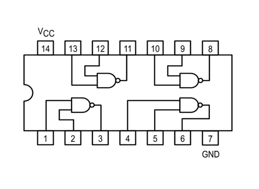
7400 NAND Gate IC Pin Out
7474 Dual D-Type Flip-Flops IC Pin Out